
Last week Lisa and I travelled over to Western Australia to complete a consultancy in the humid south west.
A few years back, soon after purchasing this historic property, the owner’s had a local contractor build an earthen barrier dam across a valley that runs through the property. This embankment holds behind it some 35ML of good quality water.
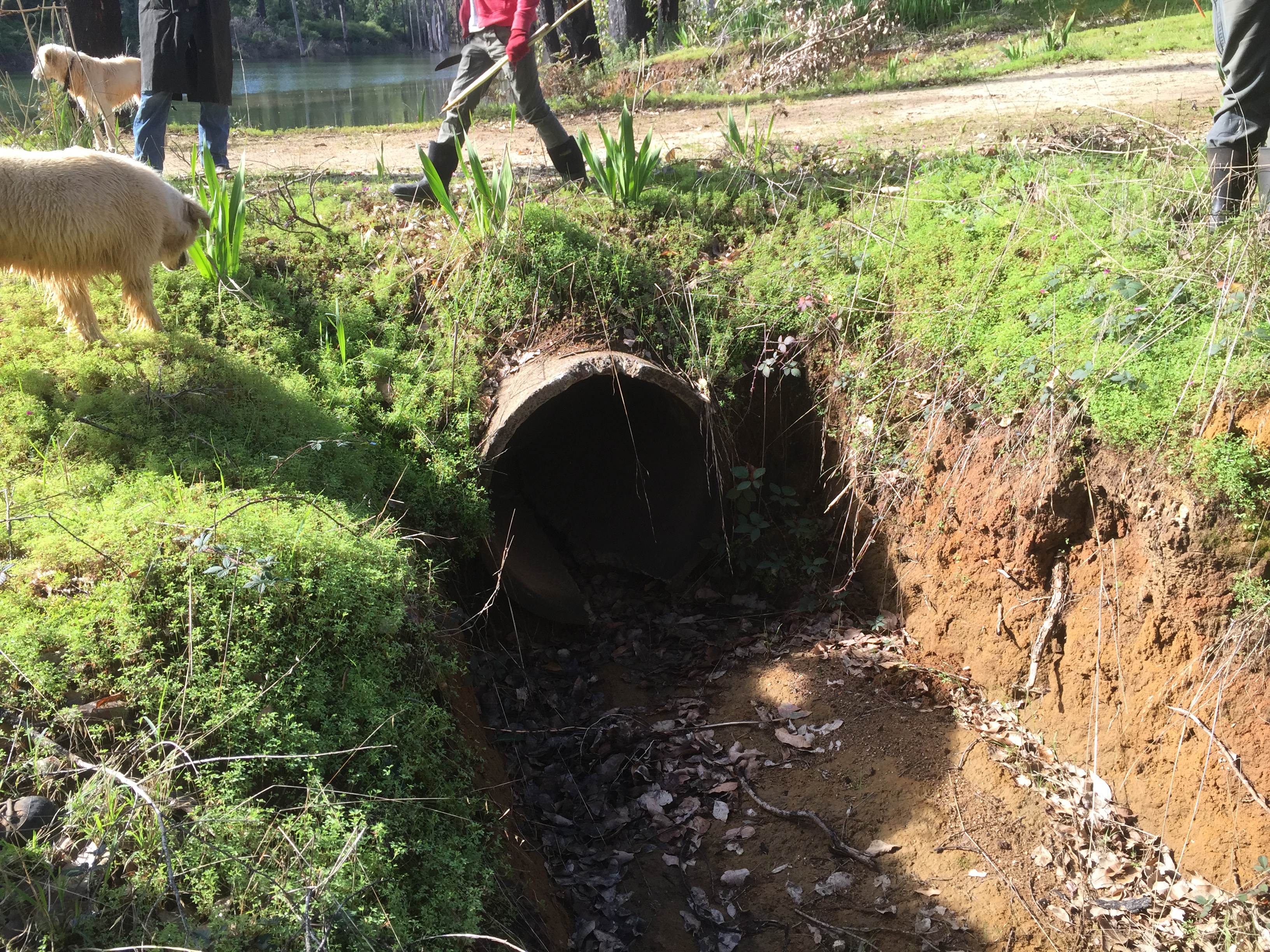
The new dam filled well and all was good and then a good rain fell and water went over the embankment. The 6m wide overflow and 1m diameter supplementary concrete ‘trickle’ pipe were not sufficient to take the flow of water.
So last week the subject of ‘the overflow’ was on our client’s to-do list for our consultancy. First thing I asked was the size of the catchment. The client didn’t know — he’d hired a contractor and presumedly he didn’t know or investigate either.
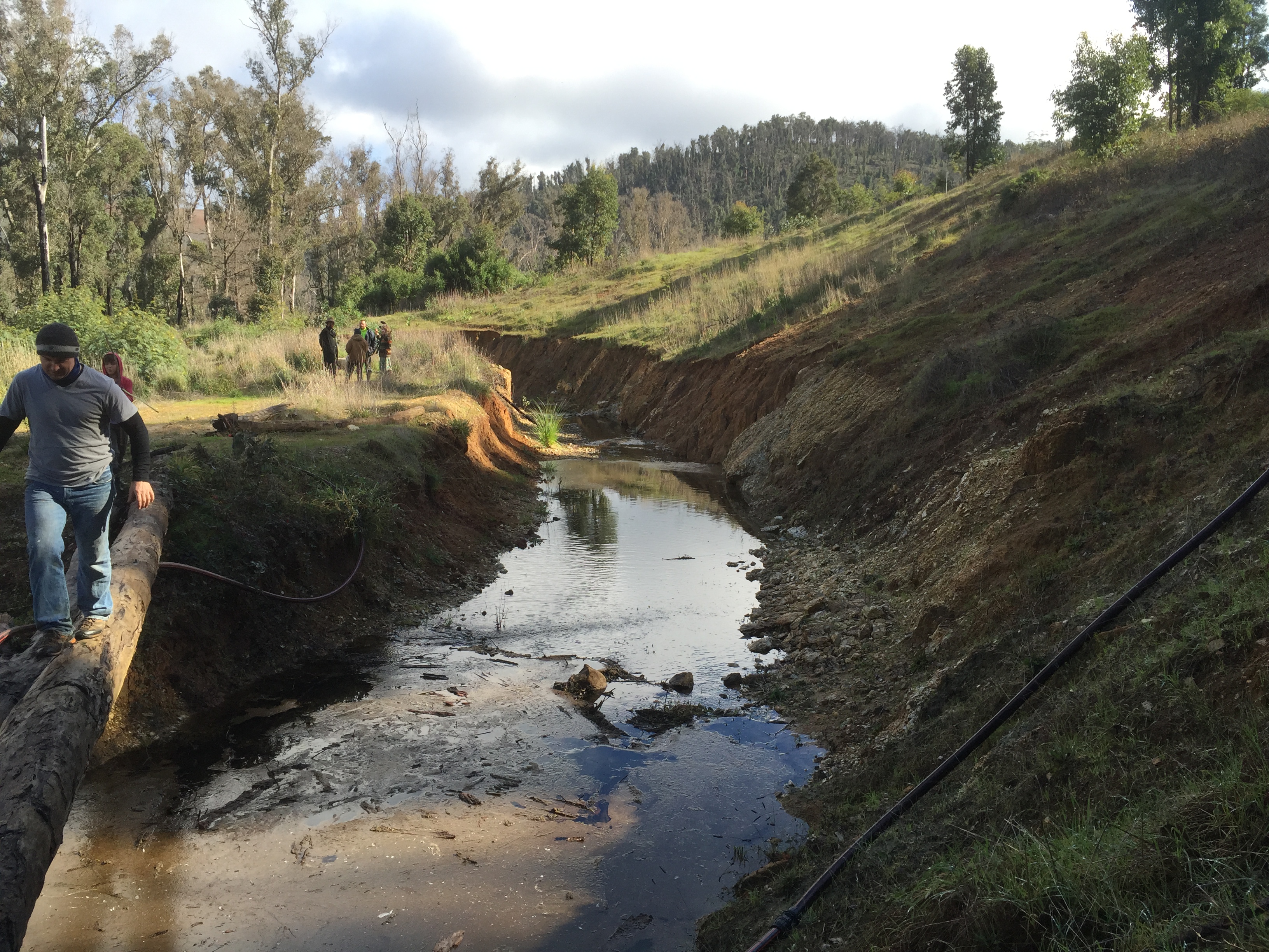
I then inspected the embankment and the overflow structures. Its mid-winter and the valley is running water — interesting enough as most valley’s don’t run water for months — the main overflow is running water across its full width about 15cm deep. Unusually the trickle pipe is well above the main overflow and on inspection its perhaps just as well as the pipe is heavily cracked near the outlet and the 1.4m wide x 1m deep earthen box channel running out of it has a 1.5m drop at the end of its 20m length.
I am concerned about this embankment and the overflows. That water has gone over the embankment is a concern, though not unsurmountable by any means given the favourable site characteristics.
What to do?
1. Catchment Area? 5869 hectares or nearly 14,500 acres!
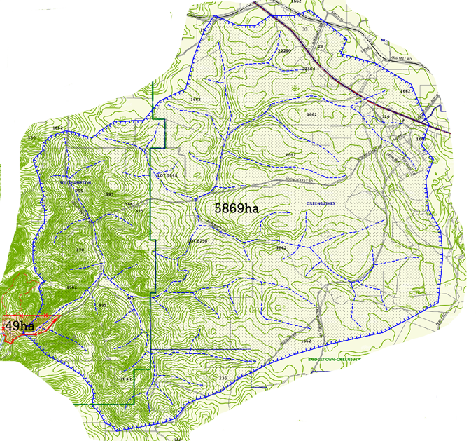
Source: www.Landgate.wa.gov.au
GIS: Regrarians (Darren J. Doherty)
2. Total Catchment Flow? 4401ML/year (750mm rainfall/year)
3. Required Overflow Width? 76m — according to a simple formula from Ken B. Yeomans (Keyline Designs) of √Catchment Area (ha) — this equates to the width of the valley floor at the embankment location. The late K.D. Nelson’s classic, ‘Design and Construction of Small Earth Dams’ (Inkata, 1985), suggests that this area is in the ‘#3 Flood Zone’. For a 100ha catchment in this zone the recommended overflow width is 7.9m — this catchment is nearly 60 times this size! The main channel of this valley is about 15 metres across and with reinforcement (lining etc.) I am confident that a new overflow width of 20m would suffice — that said we’ll definitely consult with a suitably experienced and qualified civil engineer!
4. Build New Overflows — After consulting with a civil engineer its likely we’ll go with the following scenarios:
- Build a new 15-20m wide overflow either in the centre of the embankment or to the opposite side of the current overflow. The slope angle on the side of the current overflow is 40˚ plus — whereas the other side has a slope of less than 5˚, making it a much more suitable site for a overflow. This overflow should be lined with a base of rip rap (i.e. 10-20cm diameter rock) over a layer of geotextile. The edges of the overflow would be retained with either farm-harvested timber ‘sleepers’ (i.e. 25cm x 4cm) OR a concreted rock wall.
- Install 2 new recycled plastic (PE) trickle pipes. These would be 50-60cm in diameter and judging by the base flow of the valley would take most of this flow. These pipes would terminate at the original valley floor over an apron of rip rap covered geotextile.
- These trickle pipes would be set to drop the current water level by approximately 50cm. The current freeboard height for this embankment is approx. 1m, which for a dam of this catchment and fetch (i.e. the length of water from the embankment to the furthest shore) should really be 1.5m.
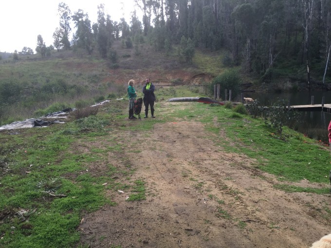
5. Remodel Embankment — some slumping has occurred across the width and breadth of the embankment and there is approximately a 75cm height difference from one side of the top of the wall to the other. Ideally their should be a rise to the centre of the wall in both directions. This would be the case if there was a centrally placed overflow as well.
6. Grass the Embankment — place a 2cm thick layer of weather damaged grass hay across the entire wall, including the batters where bare soil exists.
Other Possibilities?
With the 6-8 months of flowing water and the relatively gentle slope of the valley floor (i.e. 1-2˚) this site is well suited to energy generation via a water wheel. It is also well suited to running a Glockemann Pump or similar hydraulic ram.
Conclusion:
I am encouraged by the fact that the situation is more stable than it might otherwise be. This dam has a very large and relatively high rainfall catchment. Structures with bigger catchments and flood flows have been built for centuries and have survived with minimum maintenance. In most cases these structures started with solid engineering and that means due diligence…This didn’t happen in this case, however I am sure that we can do what’s needed to make this dam do its duties for many centuries to come too.